Primary Distribution Network
Category : electrical
To address the issue of Primary Distribution Network, we first need to comment on Transformer Distribution Station, also known as Substation.
The Distribution Transformer Station aims to lower the Transmission or Subtransmission voltage to Distribution voltage levels.
As specified in the electrical construction project, we will know the output voltage of the Distribution Transformer Station
Distribution Transformer Station Output Voltage as well as Voltage Class are given below:
Class Output Phases
5 kV 3.8 kV ABC
15 kV 13.8 kV DEF
25 kV 24.5 kV GHI
35 kV 34.5 kV JKL
For design purposes, the 5 kV Voltage Class is no longer used as it requires high gauge cables because the lower the voltage the higher the electric current will be, and the cable gauge will determine the electric current.
We must also take into account the voltage value over the length of the circuit for the purpose of calculating voltage drop.
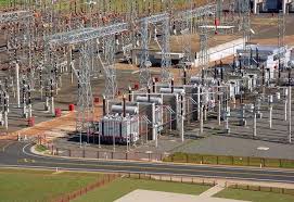
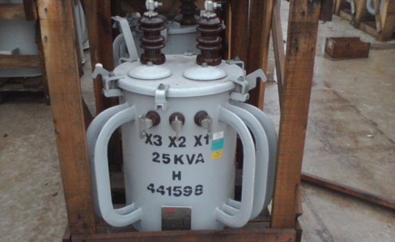
Distribution Transformer Station
Depending on the characteristics of the region, the Transformer Distribution Station may be aerial or underground.
According to the installed load and the forecast for the next years, the Voltage Class of the Distribution Transformer Station is determined.
The nomenclature of the primary circuits is composed of the acronym of the Distribution Transformer Station followed by the circuit number, knowing that the 5 kV Voltage Class is composed by two numbers, the 15, 25 and 35 kV by three numbers. 15 kV begins with number 1, 25 kV with 2, and 35 kV with 3.
Examples:
1 – A Distribution Transformer Station whose voltage is 5 kV, the circuit “0” will be XXX-00, the “1” will be XXX-01, “2” will be XXX-02, and so on.
2 – A Distribution Transformer Station whose voltage is 15 kV, the circuit “0” will be XXX-100, the “1” will be XXX-101, “2” will be XXX-102, and so on.
3 – A Distribution Transformer Station whose voltage is 25 kV, the circuit “0” will be XXX-200, the “1” will be XXX-201, “2” will be XXX-202, and so on.
4 – A Distribution Transformer Station whose voltage is 35 kV, the circuit “0” will be XXX-300, the “1” will be XXX-301, “2” will be XXX-302, and so on.
Pointing out that all primary distribution circuits ending with “0” or “1” are distress circuits and are only live (unloaded), and will only be used in emergency situations.
At the exit of the Distribution Transformer Station, in its extension and in the encounters with different primary circuits, we have the circuit switching knife keys, which can assume the state NO – Normally Open or NC – Normally Closed, according to the position in which is in the circuit.
Whenever the knife switch is in “vis-a-vis” function (meeting of two different primary circuits), it will be in the NO position.
At the exit of the Distribution Transformer Station and in the trunk (main circuit) of the primary, it will be in the NC position.
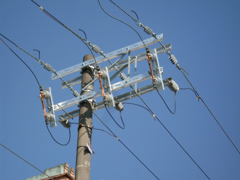
Normally Closed Knife Wrench – NC
Normally Open Knife Wrench – NO
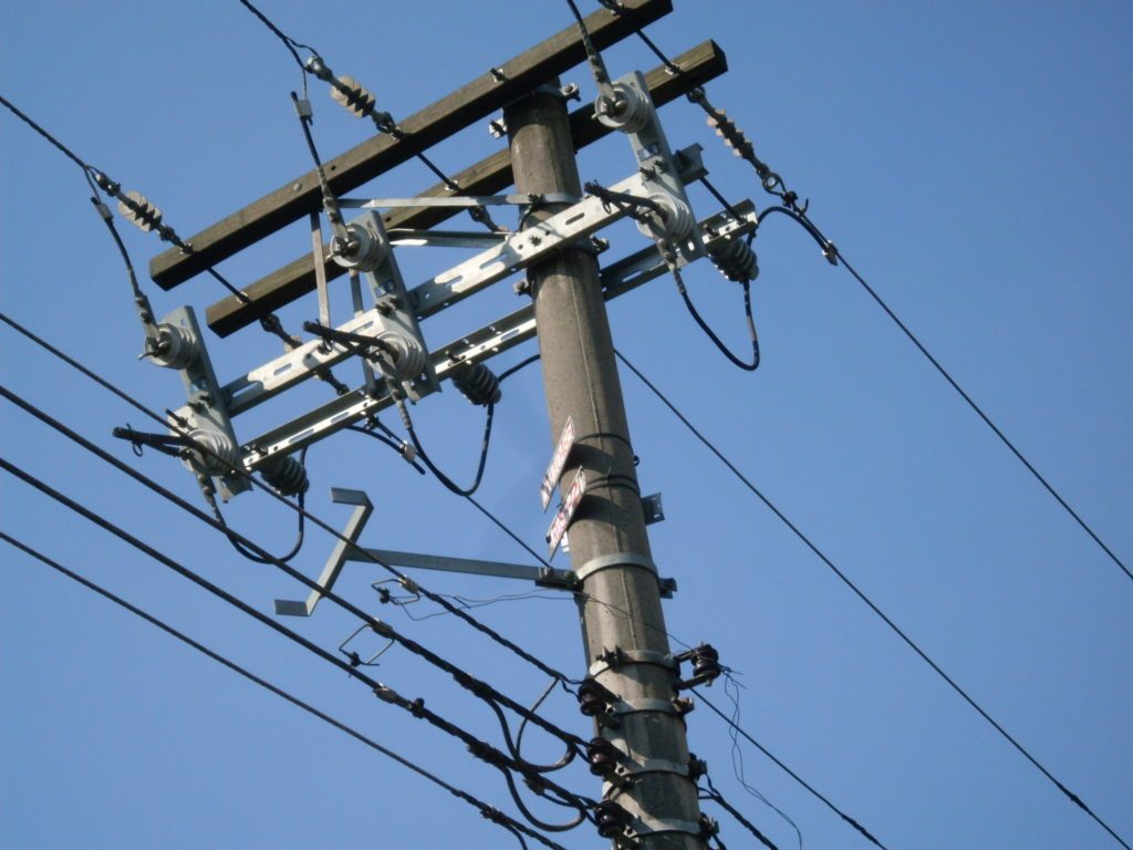
We also find in the primary circuit automatic reclosers for protection and operation, voltage regulators, capacitor banks, and branch lines, where the fuse switches, also known as Matheus switch, are located for protection and operation of circuits.
Fuse Switch Set
In the knife, fuse knife and fuse keys we will find the identification plates of the primary circuit to which such equipment belongs. If it is a vis-a-vis knife wrench we will find on one side of the set the identification of one of the circuits, and on the opposite side the identification of the other.

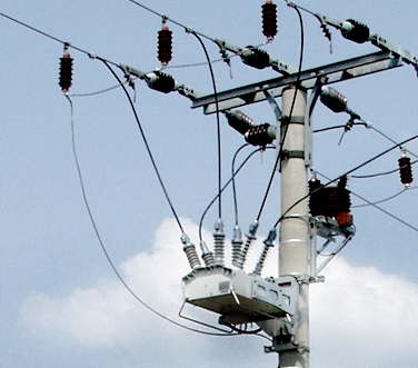
Mains Identifications
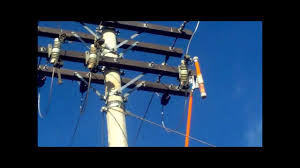
Identifying from top to bottom we have:
A, B and C – Primary Phases
D – Neutral conductor
E – Fuse switch or Matheus switch
F – Fuse switch holder
G – Delta System Single Phase Transformer
H – Secondary distribution network
J – Secondary Connection Extension
K – Telephone network
Adolpho Eletricista – Your Electrician in São Paulo – SP!
Electrician residential, real estate, commercial and industrial.
I attend in São Paulo, Greater São Paulo and South Zone of the São Paulo – BR.
![]()