ELETRICISTA EM SÃO PAULO 11 968984344 ELETRICISTA EM SANTO AMARO. Residencial, Industrial e Predial. Câmeras, Infraestrutura, Cerca Elétrica. Construção e Reforma de Padrão de Entrada, Reformas Industriais e Empresariais, ENTRADA PRIMÁRIA.
Some frequent questions from site readers and professionals in the area.
Do three-phase equipment manufactured for the Star System work on the Delta System? Both motors and resistors operate normally in the Delta System. Only the motor connections must be performed by a qualified professional to avoid damaging the motor.
Is the Delta System in practice the same as the Triangle? Delta system and triangle is the same thing. It is called a triangle because the representation of the Greek letter delta is a triangle.
One of the differences between the Delta Three Phase System is that the fourth phase (S phase) has higher voltage than the neutral? Yes. The nominal voltage of the fourth phase (phase S) with respect to the neutral is 200V, while in the star system the phase voltages are balanced (127V between phase and neutral).
I purchased a machine for Star System 220V three phase. When I explained that the three-phase Delta System is here, the supplier did not know how to inform, because it does not know the System. Several machines manufactured for the Star System are installed in the Delta System, however it is necessary to make the necessary conversions of connections by a qualified professional. There are some connections that differentiate the Delta System from the Star System. It is necessary to check the type of connection of the motor, which can be connected in various ways, according to the wiring diagrams stamped on the nameplate.
Can the same three-phase machine that binds to the Star System be connected to the Delta System? If the machine came from the factory to work on star it is necessary to adapt the connections to delta system. The operating system of the machine is powered at 127 or 220 V, so it is indifferent to be delta or star to the HMI and CLP. Who works in the three phase is only the motor and some types of resistors that can be connected in delta.
The neutral of the Delta and Star System is the same, as well as the secondary and primary distribution network. Every neutral grid is interconnected and grounded at specific points.
As more questions arise from readers, professionals and customers, will be added in this article as a review.
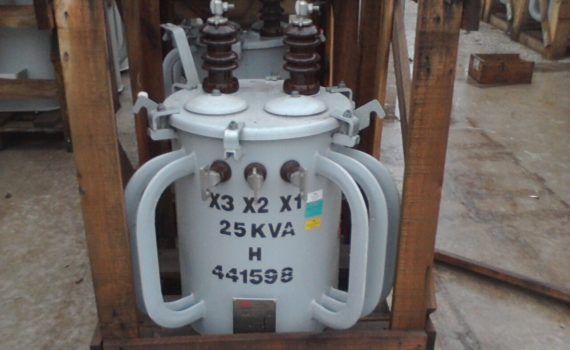
Delta (Triangle) System transformers are single phase – powered by only one primary phase. The nominal voltage between phase / neutral is 115 V. The nominal line voltage – phase / phase – is 230 V. The calculation for line voltage in the Delta System is: VL = 2. VFN Where: VL = line voltage VFN = phase / neutral voltage In the figure below, we have the example of a delta system transformer, powered at 13.8 kV. How to know the supply voltage? Simple: The primary phase of the traction power supply is phase D. Remembering Class 5 kV – Working voltage – 3.8 kV – Phases A, B, C. Class 15 kV – Working voltage – 13.8 kV – Phases D, E, F. Class 25 kV – Working Voltage – 24.5 kV – Phases G, H, I. Class 35 kV – Working voltage – 34.5 kV – Phases J, K, L. According to the letter that defines the stage in which the equipment is connected, we know the Voltage Class and the Voltage of Power. According to the scheme below, we find that the primary bushing H1 is connected in phase D and the bushing H2 is grounded to generate potential difference (ddp) between the ends of the primary coil in order to generate magnetic field and lower the voltage across of the secondary coil. A fuse switch (Matheus) must always be installed between the phase and the bushing H1 of the transformer. The capacity of the fuse link will be determined according to the power
Delta Light System
The secondary coil has three tapping points, x1, x2 and x3, where x1 and x3 are the ends of the coil and x2 is the center tap, from which the neutral is generated – zero potential under ideal conditions. It is practically impossible to keep the neutral conductor at potential ‘zero’ due to the huge unbalance of loads existing in the Electric Power System. GRADES: 1 – All the neutral grid of the electric utilities are interconnected and grounded at certain points, including in the Transformer Distribution Stations (DTEs), also known as Substations, regardless of whether the System is Delta or Star. 2 – The Neutral of the primary distribution circuit is the same as the secondary circuit. There are no two Neutral (primary and secondary) conductors, only one, called the General Neutral. The entire neutral grid is grounded in order to keep the neutral as close as possible to the zero potential. The Delta Light System is efficient only for residences, businesses and small businesses that do not need the fourth phase (fourth because the neutral is considered as phase) to work. When the client needs the fourth phase, with the largest motor up to 5 CV, the Delta ‘opens’, as shown below.
Open Delta System
In order to ‘open the Delta’, another single-phase transformer – F1 – but connected in another primary phase – phase E – is added, except that x2 will remain open, and the connection scheme of x1 of the LIGHT must be obeyed the x3 of FORCE, or x3 of the LIGHT with the x1 of FORCE.
If there is an inverted connection, x1 with x1 and x3 with x3, the motors will turn upside down and will be damaged.
The neutral phase and line voltage voltages remain the same, 115/230 V, but the nominal voltage of the fourth phase with the neutral will be 190 V, and phase voltages with 4th phase will be 230 V nominal.
The 4th phase ONLY must be used to power three-phase motors and loads, NEVER to supply single- or two-phase loads, due to the difference in nominal voltage and phase angle and phase 4 voltage phase angle values.
If this happens, there will be equipment burning.
Delta Open Connection Scheme
Closed Delta System
The most frequent question is: "how do you get to the value of 200 V between neutral and 4th phase?"
Analyzing the above scheme, we can verify that we have 1/2 coil of the LIGHT transformer (from x2 to x1) plus 1 entire coil of FORCE 1 (from x3 to x1), totaling 1 coil and 1/2, which generates 200 V between NEUTRO and phase 4.
The FORCE traction must always be of less power than the light traction, or at the maximum of the same power.
When the customer has to drive motors above 5 hp, the Delta must be 'closed', obtaining greater power from the transformer bank.
Closed Delta System
In order to 'close' the Delta, one more single-phase F2 is added, fed by another primary phase (F).
The nominal voltages of neutral phase, line and phase 4 do not change.
The connection diagram should be carefully observed: if x1 of F1 is connected in the 4th phase, x3 of F2 must also be connected to 4th phase, and x1 of F2 connected to x3 of LIGHT.
If the x3 of the F1 is connected in the 4th phase, the x1 of F2 must be connected to the 4th phase and the x3 of the F2 connected to the x1 of the LIGHT. If there is an error in the connections, x3 of F1 with x3 of F2 and x1 of F2 connected with x1 of the LIGHT will cause a short circuit between phases, and when it is connected the Closed Delta will burst the protective fuse links of the three phases of the bank of trafos and the three circuit protection fuses. If the circuit is protected by Auto or Sectionalizer, they will operate and disconnect the primary circuit. If there is no protection in the circuit before the traffic bank, you will turn off the primary circuit in the Transformer Distribution Station (substation).
The forces of FORCE must be of equal and inferior power or at most equal to the trafo of LIGHT.
Who will determine the power of the trafos to be installed will be the technical department of the concessionaire after analysis of the electrical design and relation of loads presented by the customer when request of connection, addition of load or modification.
Delta System transformers are connected in the same primary phase. In these cases, there are two LIGHT transformers connected in parallel and their powers add up. This procedure is used when a higher power bank is needed in the LIGHT and there are no commercially available trains at this power.
Example: A bank of 200 kVA LIGHTs is required. Two parallel 100 kVA trains are installed to achieve 200 kVA.
The Delta trafets in the distribution networks are 5, 10, 15, 25, 37.5, 50, 75 and 100 kVA, but currently only 10, 25, 50 and 100 kVA are commercially available.
According to the Ordinance of ANEEL – National Agency of Electric Energy – Brazil, from the 90’s onwards, it was prohibited to design Transformer Distribution Stations of the Delta System, allowing only maintenance in existing ones. The Transformer Distribution Stations designed as of the force of the Ordinance shall be of the Estrela System, in order to improve the load balancing of the primary distribution circuits and the transmission circuits.
Advantages of the Delta System
The only advantage of the Delta System is the cost of implementing the system, because with only one primary phase secondary voltage is obtained to serve residential, commercial and business customers that do not need a three-phase network.
At a much lower cost than the Star System, the goal is achieved. Disadvantages of the Delta System The Delta System generates a very large load unbalance in the Electric Power System – SEP, requiring constant electrical current measurements of the primary distribution and transmission phases, often being necessary to transfer transformers from one phase to another in order to balance the loads of circuits.