Voltage Regulator – Medium Voltage

  • -

Voltage Regulator – Medium Voltage

Voltage regulators are equipment installed on long branches of primary circuits that feed low-density regions, particularly in suburban and rural areas where the natural voltage regulation of the circuit is impaired.
The regulators are single phase or three phase, which allows their use in single, two or three phase primary circuits.

Voltage Regulator

It is programmed to start when the primary voltage is below or above the preset primary voltage limits (+ 10% or -10%).

Single-phase voltage regulators can be installed on single-phase lines or by forming two- or three-phase mounted banks in the primary networks. Assembly requires the identification of the source / load side.

The control of the voltage regulator is made by a voltage level and voltage drop compensation sensor of the considered circuit section that allows the automatic adjustment of the regulator position, raising or lowering, in the voltage regulator output, the voltage which receives at the input such that theoretically at a certain point of the primary circuit the voltage is constant.


Single Phase Recloser Bank

Voltage regulator compensation is calculated so that the maximum output voltage of the first downstream installed transformer does not exceed the maximum operating voltage, and that the output voltage of the last transformer does not fall below the minimum operating voltage.

 Definitions

Nominal voltage of a system or circuit

It is the nominal value assigned to the system or circuit of a given voltage class for the purpose of its convenient designation.

Nominal voltage refers to line voltage (phase-to-phase voltage), not phase to neutral voltage, and applies to all parts of the system or circuit.

Service voltage

It is the voltage to which the operating characteristics and performance of the equipment are referred.

Regulated Circuit

It is the circuit connected to the voltage regulator output and in which one wishes to control the voltage, phase relationship or both. The voltage can be kept constant at any point of the regulated circuit.

SHORT Adolpho Eletricista

Adolpho Eletricista – Your Electrician in São Paulo – SP!

Electrician residential, real estate, commercial and industrial.

I attend in São Paulo, Greater São Paulo and South Zone of São Paulo – BR.


  • -

Electric Power System – EPS

EPS – Electric Power System is the set of all facilities and equipment for the generation, transmission and distribution of electricity up to and including measurement.

Electric Power System – EPS

The generation is responsible for producing the electrical voltage.

The Electric Power Generating Plants can be:

Hydroelectric


Thermoelectric

Nuclear

Solar

Geothermal

Tidal Wave

Wind power

Biomass

After generation in AC, the voltage goes through a process of elevation to be transmitted at high voltage levels, due to lower losses and lower implementation cost of the transmission system, because the higher the voltage, the lower the electric current.

As the cable gauge determines the electric current and voltage drop, the higher the transmission voltage the smaller the cable gauge.

Transmission and subtransmission voltage values: 750; 500; 230; 138; 88; 69 kV.

The 69 and 88 kV voltages are considered subtransmission, ie the voltage values ​​in a ETT – Transmission Transformer Station, to supply customers in subtransmission voltage.

When arriving at ETDs – Distribution Transformer Stations, also known as substations, the transmission voltage or subtransmission, depending on the supply voltage of the ETD, is lowered to primary distribution voltage values ​​(34.5, 24.5 and 13, 8 kV). In some regions there is still a primary distribution voltage of 3.8 kV, but it is in extinction phase.


Distribution Transformer Station – DTS

The primary distribution circuits in the Electric Power System are identified according to the voltage class and working voltage, as follows:

Class 5 kV – Working Voltage – 3.8 kV – Circuit ID beginning with “0”


Example: Circuit 03, 04, 05.

Class 15 kV – Working Voltage – 13.8 kV – Circuit ID beginning with “1”

Example: Circuit 103, 104, 105.

Class 25 kV – Working Voltage – 24.5 kV – Circuit ID beginning with “2”

Example: Circuit 203, 204, 205.

Class 35 kV – Working Voltage – 34.5 kV – Circuit ID beginning with “3”

Example: Circuit: 303, 304, 305.

All ETDs have a name and an acronym. In the case of Capuava ETD, acronym CAP. ETD Santo André, acronym SND, and the nomenclature of the primary circuits will be:

SND – 03 – SND – 04 – SND – 05, because the primary distribution voltage of this ETD is 3.8 kV.
CAP – 103 – CAP – 104 – CAP – 105, because the primary distribution voltage of this ETD is 13.8 kV, and so on.
Primary distribution circuits with end ’00’ and ’01’ are distress circuits and are not used to distribute voltage to urban centers like the others. They are only in ‘voltage’, unloaded. If a problem occurs in any other circuit, such as a transformer failure, for example, the relief circuit will assume the load of the failed circuit through knife-wrench maneuvers.


Primary Distribution Circuit

Upon arriving at the electricity consumption centers, the primary distribution voltage may serve industrial customers and large Medium Voltage customers through the primary cabin, a contract to be entered into with the electricity concessionaire through electrical projects and other documentation.

Primary Cabin

To serve low voltage customers – BT, primary distribution voltage values ​​should be lowered to secondary distribution voltage values ​​and delivered to the customer input standard.

The utility is responsible for supplying the voltage value in accordance with the Norms and Standards to the customer input standard circuit breaker.

Responsibility for the construction and maintenance of the input standard is the responsibility of the customer, as well as the conservation of the watt hour meter that will be his responsibility. In case of misuse or vandalism, the customer will be responsible for the consequences.

Responsibility for periodic maintenance of the watt hour meter and repair in the event of damage due to wear of the equipment lies with the utility.

The supply voltage values ​​in the delta and star system can be checked in the Delta System and Star System articles.

SHORT Adolpho Eletricista

Adolpho Eletricista – Your Electrician in São Paulo – SP!

Electrician residential, real estate, commercial and industrial.

I attend in São Paulo, Greater São Paulo and South Zone of São Paulo – BR.


  • -

Losses in the Electric Power System

The Electrical Power System consists of generation, transmission and distribution. Losses in the Electric Power System refer to the generated electric energy that passes through transmission lines and distribution networks, but which is not commercialized, either for technical or commercial reasons.


Electrical Power System

The transmission of energy, whether in transmission or distribution, inevitably results in technical losses related to the transformation of electrical energy into thermal energy in conductors (joule effect), losses in transformer cores, dielectric losses, etc.

Non-technical or commercial losses stem mainly from theft (clandestine connection, direct network diversion) or energy fraud (tampering in measurement), popularly known as “cats”, metering and billing errors.

Losses in the Electric Power System are controlled through the automation of the electric system and power factor control (PF), according to the ANEEL Ordinance, which establishes PF = 0.92. This control against the big consumers is done with great seriousness and those who escape the limit of 0.92 will bear a heavy fine.

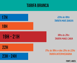
Another way to control losses is by using peak and intermediate rush hour rates. Many customers chose to use the Generator Group that was inoperative at these times, putting it to operate, in order to reduce the consumption of electricity at these times. The amount that is spent on diesel is much lower than with electricity tariffs and fines.

End Time

This schedule is composed of a period of three consecutive hours that is adopted between 5:00 pm and 10:00 pm, including holidays, except Saturdays and Sundays. These times can vary from concessionaire to concessionaire, according to the region in which it is established.

Intermediate Hours

It is the period comprised of an hour before and an hour after the rush hour.

Off Time

It’s the remaining 19 hours of the day.

The white tariff for residential customers is in force, which is the incentive for not using high power equipment, such as shower, electric faucet and iron, during peak and intermediate hours.

The white tariff is a new tariff option that signals to consumers the variation of the energy value according to the day and time of consumption. It will be offered to consumer units that are serviced at low voltage (127, 220, 380 or 440 volts, denominated group B) and to those belonging to group A that opts for the low voltage tariff. The measure was approved in a public meeting of the Board of Directors of ANEEL.

The star system transformers projects, as mandated by ANEEL, also contribute to the reduction of losses because it is a more balanced and reliable system than the delta system. The goal is to eliminate, over time, the delta distribution system.

Inspections with thermovision to check and subsequently eliminate hot spots – current leakage – occurring in compromised connections, equipment or insulators are constant practices, as well as load balancing between primary phases.

The construction of new DTEs and new circuit designs, including changing the distribution voltage class from 5 kv to 15 kv or 25 kv, according to the region, are prime factors to reduce losses in the Electric Power System, since the higher the voltage the lower the current and, consequently, the lower the losses.

Moving to compact primary network – space cable – is also a determining factor for loss reduction. The Department of Distributed Engineering analyzes and controls all primary circuits, and when necessary intercedes for its improvement.


Technical Losses

Technical Losses in Distribution

The distribution system is divided according to the network segments (high, medium and low voltage), transformers, connection extensions and meters. Specific models are then applied for each of these segments, using simplified information of existing networks and equipment, such as length and gauge of conductors, power of transformers and power supplied to consumer units. Based on this information, it is estimated the percentage of efficient technical losses related to the energy injected into the network.

Non-technical losses

The non-technical losses are calculated by the difference between total losses and technical losses. The regulatory values ​​of non-technical losses are calculated by ANEEL by a methodology for comparing the performance of distributors, observing efficiency criteria and the socioeconomic characteristics of concession areas .

Sources: ANEEL – National Electric Energy Agency

ENEL Distribuição

SHORT Adolpho Eletricista

Adolpho Eletricista – Your Electrician in São Paulo – SP!

Electrician residential, real estate, commercial and industrial.

I attend in São Paulo, Greater São Paulo and South Zone of the São Paulo – BR.


  • -

GTD – Generation, Transmission and Distribution of Electric Energy

When we are dealing with GTD – Generation, Transmission and Distribution of Electric Energy, we refer to the SEP – Electrical Power System, which is defined by “all the materials and equipment necessary for the Generation, Transmission and Distribution of Electric Energy to the final consumer, including”.

The electric power is generated in the Power Plants, which can be: Hydroelectric, Thermoelectric, Nuclear, Solar, Wind, Geothermal and Tidal Power.


Hydroelectric plant

After generation, the voltage must be raised to transmission voltage levels, which is done in an Transformer Transmission Station, located next to the Generating Plant. It is a Voltage Lifting Substation.
The voltage is raised to 138 kV, 235 kV, 440 kV, 750 kV at the 60 hertz (AC) frequency, and there are some transmission networks operating at 1 MV on an experimental basis.
Some transmission networks work in DC until certain point of the circuit, being converted back to AC.


Tidal power plant

HVDC systems are an alternative for the transmission of large blocks of energy (over 1500 MW) over long distances (over 1000 km).

In the 1950s, the transmission voltage was 50 kV, then it was changed to 69 kV and some years later to 88 kV. Today these voltage values ​​are considered subtransmission voltage.

After the Transmission, there is a Transformer Transformer Station, where the voltage is transformed into subtransmission values ​​to feed the Transformer Distribution Stations and Substations of large industries.

Transmission

The reason for increasing the value of the transmission voltage over the years was the increase in the demand for electric power, caused by the population increase, industrial and business growth and the range of consumer electronics devices that appeared in the consumer market, with increasing powers high.

As an example we have the electric shower, which migrated from 3000 W to 4500 W, 5600 W, 6800 W and 7800 W. Aluminum Cable for Transmission When we talk about increased demand, we refer to an increase in electric current, which causes overload in the Electrical System of Power and Loss, requiring the increase of the working voltage to lower the current, as they are inversely proportional in the SEP.


Aluminum Cable for Transmission

Another determining factor for raising the transmission voltage is that it is possible to reduce the gauge of the electric conductors, as the current values ​​are lowered; we can not forget that the calculation of voltage drop is also a preponderant factor for the calculation of the gauge of the conductor to be used.

Upon reaching urban centers, electricity must be lowered to levels of distribution to be delivered to customers.

The whole process of distribution network operation is found in the articles Primary Distribution Network, Distribution Transformer Station, Underground Distribution Network among others in this site.

SHORT Adolpho Eletricista

Adolpho Eletricista – Your Electrician in São Paulo- SP!

Electrician residential, real estate, commercial and industrial.

I attend in São Paulo, Greater São Paulo and South Zone of São Paulo – BR.


  • -

Know the Star System of Distribution of Electric Energy

The Star System is composed of a three-phase transformer powered by the three phases of the primary circuit of electric energy distribution.

The primary bushings H1, H2 and H3 are fed by the 3 primary phases, protected by fuse switches (Matheus) and links specified according to the power of the transformer.

In the secondary output bushings X0, X1, X2 and X3, we will obtain the output voltages, as shown below:


Star System Connection Scheme

The system is powered at 13.8 kV, since the phases are D, E and F, subject discussed in the article on Delta System.

The bushing X0 corresponds to the NEUTRAL of the star system, X1 to phase A, X2 phase B and X3 phase C.

The nominal voltages between Neutral and Phase A, Neutral and Phase B, Neutral and Phase C are equal to 127 V and nominal line voltages equal to 220 V (127/220 V system).

Phases A, B and C are better known in the industry for R, S, and T.


Schematic of a star transformer

Schematic of a star transformer In the star system 220/380 V the nominal voltage between Neutral and Phase is 220 V, and the nominal line voltage is 380 V.

The expression used for voltage calculation in the three-phase system is as follows:

Where: VFN – neutral phase voltage

VFF – phase phase voltage or line voltage

V3 = 1.73 (approximate value, since it is periodic tithe)

According to the star formed by the 3 secondary coils (figure above), we notice that the phase angle between Phases A, B and C is 120º, which keeps the voltages out of phase as shown below:


Three Phase Voltage Diffusion Chart

Three Phase Voltage Diffusion Chart Author’s Note: RMS voltage, from the English Root Mean Square or Effective Value are the line or phase voltages.

Analogy between Star System and Delta System

In the Star System, because of the balanced voltages, we have been able to load loads much higher than the Delta System, which presents unbalanced voltages.

Due to the imbalance between the secondary voltages, the Delta System generates a very large load unbalance in the SEP – Electrical Power System, damaging it, whereas in the Star System, because of the balanced voltages, we can balance the loads with greater ease, keeping the SEP more stable and generating a smaller number of maintenance in the circuits of distribution, transmission and the generation of electric energy.

Conclusion

The Star System is infinitely better than the Delta System in all respects.

short  Adolpho Eletricista

Adolpho Eletricista – Your Electrician in São Paulo – SP!

Electrician Residential, Commercial, and Industrial

I attend in São Paulo, Greater São Paulo and South Zone of São Paulo – BR.


Posts recentes

Desenvolvido por : TyttoSoft (11) 9466-02599